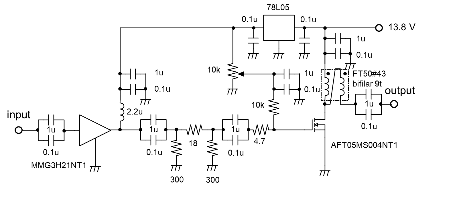
Wide band class-A power amplifier
I designed a simple and compact wideband power amplifier circuit for HF. Depending on the operating point, an output of 4~5 W can be obtained with input ~ 0.1 mW.
Configuration
Driver:MMG3H21NT1Gain 17dB、OP1dB 20.5 dBm
It is also used for TX circuits in IC-9700. Input and output impedance are almost completely matched at 50Ω without any matching circuits.
Final:AFT05MS004NT1
VDSS = 30 V, PD = 28 W
A LDMOS FET for RF power amplification with small feedback capacitance and high gain in the HF band.
Characteristics
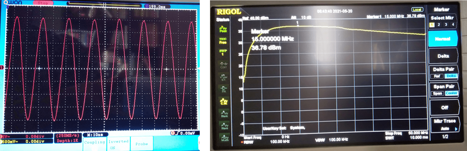
Adjust the bias current with a variable resistor not to clip output waves. The frequency dependence shown in the photo shows gain in 7~25MHz is within ± 1dB.Since the heat sink cannot be attached directly, you should take care to heating. Here, heat is made to escape to the heat sink through the PCB.
本日はリニアアンプの試作を行いました。
— JR2BMU/1 (@jr2bmu) May 19, 2021
写真の構成でドライバとファイナルの2段を実験しました。
動作点の調整はまだですが、周波数特性も良好で、出力4~5W程度なら線形性も保たれそうです😄 pic.twitter.com/5erTTTk2NE