Digital signal proccesing with a STM32 Nucleo board (3)
Last time, I set up to use signal processing with the DSP library. Here, I will design a complex FIR filter that generates a quadrature AF signal used for a PSN SSB modulator.Principle
Orthogonal audio signals are required for PSN SSB modulation. Here, I tried to generate such signals with digital signal processing. In this time, I reffered the method described here (in Japanese). If you are interested in, please check it.The outline of the operating principle is following. Because the real signal can be regarded as a superposition of ± ω complex signals (Fig. 1 (a)), when only the positive frequency +ω is taken out, the real part and the imaginary part of the signal show orthogonality(Fig. 1 (b)). Since this is independent with frequency, it provides orthogonal signals over a wide frequency range.
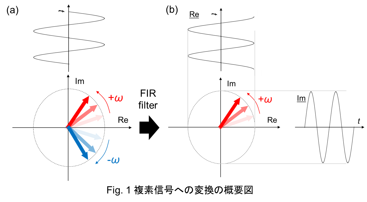
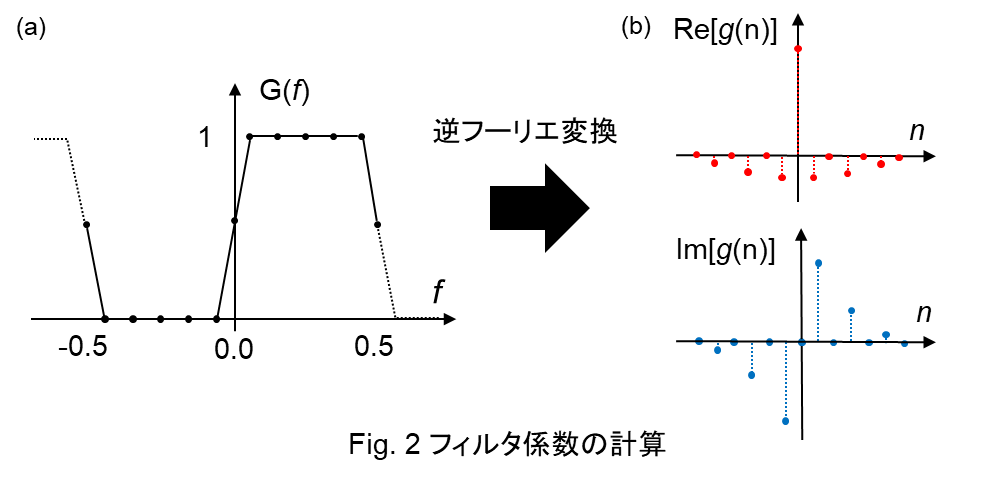
Specifically, as shown in Fig. 2 (a), a filter passing positive frequencies is implemented. The filter coefficient g (n) can be obtained by inverse Fourier transformation of the above transfer function G(ω). By applying filters R and I which has the real and imaginary part of g (n) as filter coefficient, the real part and imaginary part of Fig. 1 (b) are generated. You will get an orthogonal signal.
Setting
(1)Calculation of filter coefficientCalculate the filter coefficient (Fourier transform) with an calculation tool. Here is filter coefficient for 62 taps FIR filters(real・imaginary)
(2)Source codes
It's basically the same with last time, but there are two changes:
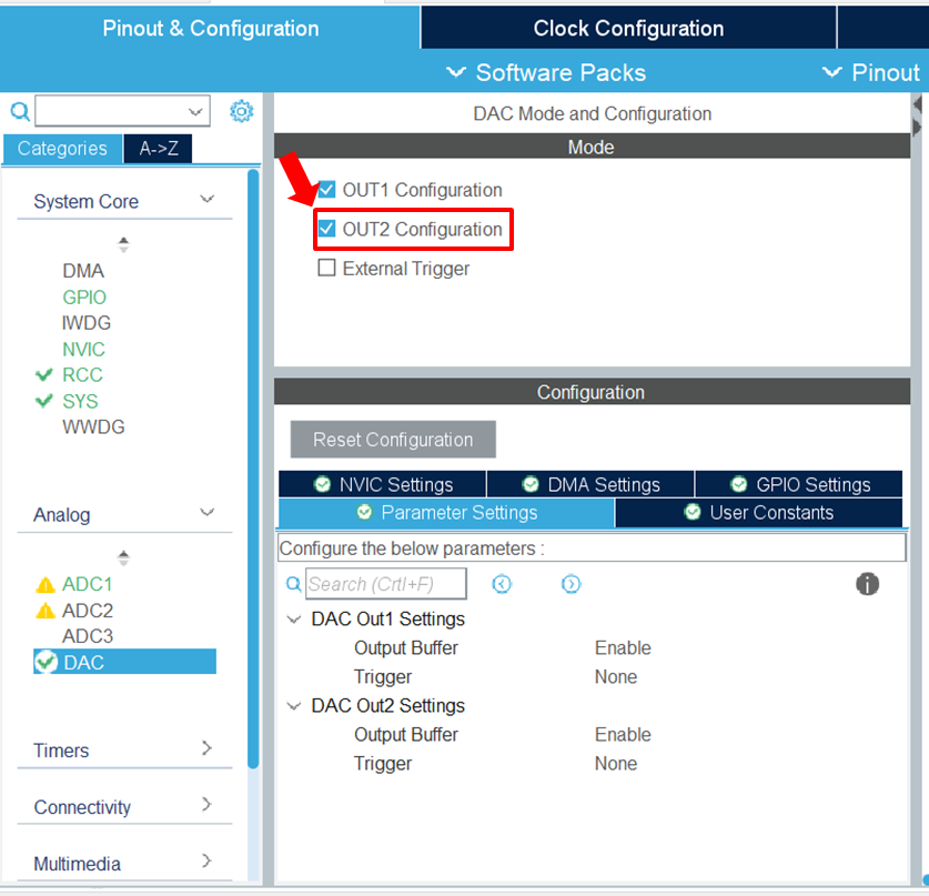
(2-1)DAC
Please activate DAC CHANNEL2, then you can use PA5 as second output pin.
/* USER CODE BEGIN 2 */
HAL_DAC_Start(&hdac, DAC_CHANNEL_1);
HAL_DAC_Start(&hdac, DAC_CHANNEL_2);
/* USER CODE END 2 */
(2-2)main function
Define two filters corresponding real and imaginary part, respectively. In "main.c", the source code up to the main() is here. Orthogonal signals are obtained at PA4 and PA5 pins.
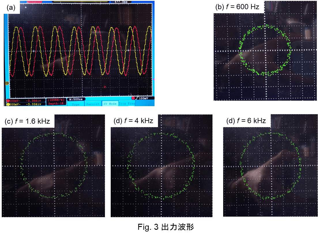
Characteristics
Fig. 3 (a) shows the output waveforms of Ch1 (red) and Ch2 (yellow) with 1kHz-input signal. In addition, Fig. 3 (b-e) shows Lissajous diagram for various input frequencies (600Hz-6kHz). You can see that output signals are orthogonal in the required frequency range.